2017년 2월 11일 토요일

Grove - Water Sensor


Grove - Water Sensor

Introduction

3.3V 5.0V Digital
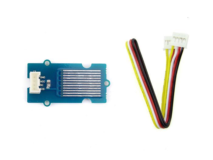
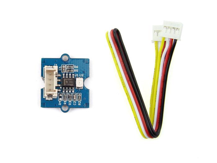
The Water Sensor module is part of the Grove system. It indicates whether the sensor is dry, damp or completely immersed in water by measuring conductivity. The sensor traces have a weak pull-up resistor of 1 MΩ. The resistor will pull the sensor trace value high until a drop of water shorts the sensor trace to the grounded trace. Believe it or not this circuit will work with the digital I/O pins of your Arduino or you can use it with the analog pins to detect the amount of water induced contact between the grounded and sensor traces.

Features

  • Grove compatible interface
  • Low power consumption
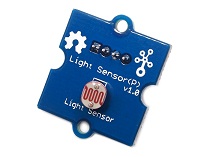
  • 2.0cm x 2.0cm Grove module
  • High sensitivity
Tip
More details about Grove modules please refer to Grove System

Applications Ideas

  • Rainfall detecting
  • Liquid leakage
  • Tank overflow detector
Caution
This device is for educational and hobby applications only. It is not intended to be used in applications where its malfunction could result in damage to property or human safety.

Specifications

ItemMinTypicalMaxUnit
Working Voltage4.755.05.25V
Current<20mA
Working Temperature10-30
Working Humidity (without condensation)10-90 %

Platforms Supported

ArduinoWioBeagleBoneRaspberry PiLinkIt ONE
Caution
The platforms mentioned above as supported is/are an indication of the module's hardware or theoritical compatibility. We only provide software library or code examples for Arduino platform in most cases. It is not possible to provide software library / demo code for all possible MCU platforms. Hence, users have to write their own software library.

Getting Started

With Arduino

Connect the module to the Basic board using any of the digital pin. You can gain the value of the signal pin. When there is water on the bare conducting wires, the value is LOW. Otherwise, it will be HIGH.
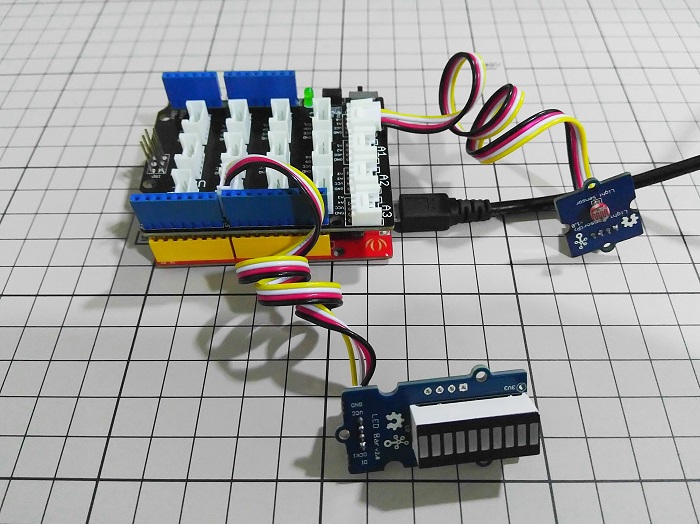
The following sketch demonstrates a simple application of using the Water sensor to control the buzzer. As the picture on the below indicates, the Water sensor is connected to digital port 8 of the Grove - Base Shield and the Buzzer is connected to digital port 12. When there is water on the bare conducting wires, the SIG pin output a LOW voltage. Then the Buzzer sounds. The hardware installation is as follows:
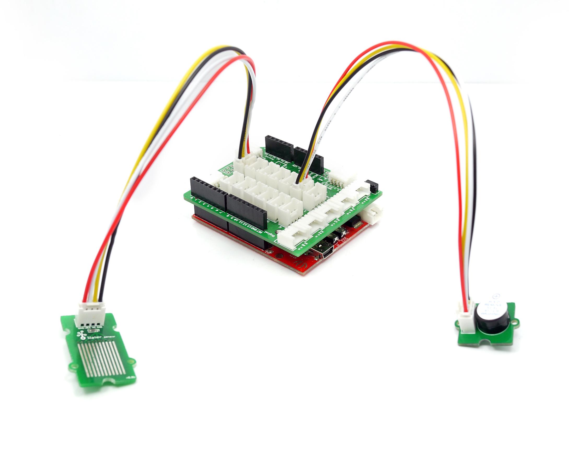
  • Then connect Arduino to PC by using a USB cable.
  • Copy and paste code below to a new Arduino sketch.
/*macro definition of water sensor and the buzzer*/ #define WATER_SENSOR 8 #define BUZZER 12 void setup() { pins_init(); } void loop() { if(isExposedToWater()) soundAlarm(); } void pins_init() { pinMode(WATER_SENSOR, INPUT); pinMode(BUZZER, OUTPUT); } /************************************************************************/ /*Function: When the sensor is exposed to the water, the buzzer sounds */ /* for 2 seconds. */ /************************************************************************/ void soundAlarm() { for(uint8_t i = 0;i < 20;i ++) { digitalWrite(BUZZER, HIGH); delay(50); digitalWrite(BUZZER, LOW); delay(50); } } /************************************************************************/ /*Function: Determine whether the sensor is exposed to the water */ /*Parameter:-void */ /*Return: -boolean,if it is exposed to the water,it will return true. */ /************************************************************************/ boolean isExposedToWater() { if(digitalRead(WATER_SENSOR) == LOW) return true; else return false; }
  • Upload the code.
  • The buzzer sounds when the sensor is damp or completely immersed in water. Have a try!

With Raspberry Pi

1.You should have a raspberry pi and a grovepi or grovepi+.
2.You should have completed configuring the development enviroment, otherwise follow here.
3.Connection
  • Plug the sensor to grovepi socket D2 by using a grove cable.
4.Navigate to the demos’ directory:
cd yourpath/GrovePi/Software/Python/
  • To see the code
nano grove_water_sensor.py # "Ctrl+x" to exit #
import time import grovepi # Connect the Grove Water Sensor to digital port D2
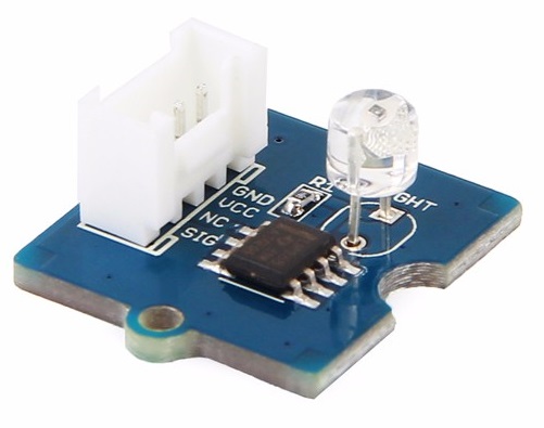
 # SIG,NC,VCC,GND water_sensor = 2 grovepi.pinMode(water_sensor,"INPUT") while True: try: print grovepi.digitalRead(water_sensor) time.sleep(.5) except IOError: print "Error"
5.Run the demo.
sudo python grove_water_sensor.py

Resources

Help us make it better

Thank you for choosing Seeed. A couple of months ago we initiated a project to improve our documentation system. What you are looking at now is the first edition of the new documentation system. Comparing to the old one, here is the progresses that we made:
  • Replaced the old documentation system with a new one that was developed from Mkdocs, a more widely used and cooler tool to develop documentation system.
  • Integrated the documentation system with our official website, now you can go to Bazaar and other section like Forum and Community more conveniently.
  • Reviewed and rewrote documents for hundreds of products for the system’s first edition, and will continue migrate documents from old wiki to the new one.
An easy-to-use instruction is as important as the product itself. We are expecting this new system will improve your experience when using Seeed’s products. However since this is the first edition, there are still many things need to improve, if you have any suggestions or findings, you are most welcome to submit the amended version as our contributor or give us suggestions in the survey below, Please don’t forget to leave your email address so that we can reply.
Happy hacking

Grove - UV Sensor


Grove - UV Sensor

Introduction

3.3V 5.0V Analog
The Grove – UV Sensor is used for detecting the intensity of incident ultraviolet(UV) radiation. This form of electromagnetic radiation has shorter wavelengths than visible radiation. The Grove - UV Sensor is based on the sensor GUVA-S12D which has a wide spectral range of 200nm-400nm. The module outputs electrical signal which varies with the UV intensity, which gives your suggestion if it is a good idea to beach today.

Features

  • High stability
  • Good Sensitivity
  • Low power consumption
  • Schottky type photodiode sensor
  • Wide response range
  • Grove Interface
Tip
More details about Grove modules please refer to Grove System

Specifications

ItemMinTypicalMaxUnit
Operating Voltage3.05.05.1VDC
Current0.31mA
Output VoltagemV
Response wavelength240~370nm
Working Temperature-30~85

Platforms Supported

ArduinoWioBeagleBoneRaspberry PiLinkIt ONE
Caution
The platforms mentioned above as supported is/are an indication of the module's hardware or theoritical compatibility. We only provide software library or code examples for Arduino platform in most cases. It is not possible to provide software library / demo code for all possible MCU platforms. Hence, users have to write their own software library.

Usage

UV sensors are used in many different applications. Examples include pharmaceuticals, automobiles, and robotics. UV sensors are also used in the printing industry for solvent handling and dyeing processes. In addition, UV sensors are also used in the chemical industry for the production, storage, and transportation of chemicals.
The fact of the UV sensor work is: In sunlight, the UV index and Photocurrent are a linear relationship.
About our Grove - UV Sensor, we have converted Photocurrent to corresponding voltage value collected by Arduino/Seeeduino. The output voltage and the UV index is linear:
illumination intensity = 307 * Vsig
where: Vsig is the value of voltage measured from the SIG pin of the Grove interface, unit V. illumination intensity unit: mW/m2 for the combination strength of UV light with wavelength range: 240nm~370nm
Note
To calculate the UV index value, please refer to US EPA. It is hard to say that the measurement from this sensor can be converted to the EPA standard UV index, but can be estimated roughly.
UV Index = illumination intensity / 200

Example

  • Connect it to A0 port of Grove - Base Shield.
  • Plug the Grove - Base Shield into Arduino/Seeeduino and connect them to PC using a USB cable.
  • The demo code is shown below.
// modified by Victor // to calculate UV index directly void setup(){ Serial.begin(9600); } void loop() { int sensorValue; long sum=0; for(int i=0;i<1024;i++)// accumulate readings for 1024 times { sensorValue=analogRead(A0); sum=sensorValue+sum; delay(2); } long meanVal = sum/1024; // get mean value Serial.print("The current UV index is:"); Serial.print((meanVal*1000/4.3-83)/21);// get a detailed calculating expression for UV index in schematic files. Serial.print("\n"); delay(20); }

Resources

Help us make it better

Thank you for choosing Seeed. A couple of months ago we initiated a project to improve our documentation system. What you are looking at now is the first edition of the new documentation system. Comparing to the old one, here is the progresses that we made:
  • Replaced the old documentation system with a new one that was developed from Mkdocs, a more widely used and cooler tool to develop documentation system.
  • Integrated the documentation system with our official website, now you can go to Bazaar and other section like Forum and Community more conveniently.
  • Reviewed and rewrote documents for hundreds of products for the system’s first edition, and will continue migrate documents from old wiki to the new one.
An easy-to-use instruction is as important as the product itself. We are expecting this new system will improve your experience when using Seeed’s products. However since this is the first edition, there are still many things need to improve, if you have any suggestions or findings, you are most welcome to submit the amended version as our contributor or give us suggestions in the survey below, Please don’t forget to leave your email address so that we can reply.
Happy hacking

Grove - Light Sensor


Grove - Light Sensor

Introduction


enter image description here
The Grove - Light sensor a photo-resistor(light dependent resistor) to detect the intensity of light in the environment. The resistance of photo-resistor decreases when the intensity of light increases. A dual OpAmp chip LM358 on board produces voltage corresponding to intensity of light(i.e. based on resistance value). The output signal is analog value, the brighter the light, the larger the value.
This module can be used to build a light controlled switch i.e. switch off lights during day time and switch on lights during night time.
Warning
The light sensor value only reflects the approximated trend of the intensity of light, it DOES NOT represent the exact Lumen.

Version Track

This document applies to the following version of products:
VersionReleased DateHow to buy
Grove - Light Sensor 1.0Apr28, 2013enter image description here
Grove - Light Sensor(P)2014enter image description here
Grove - Light Sensor(P) V1.1Aug, 2016enter image description here

Features


  • Analog value output
  • High reliability and sensibility
  • Small footprint
  • Recognize wider spectrum
Tip
More details about Grove modules please refer to Grove System

Platform Support

ArduinoWioBeagleBoneRaspberry PiLinkIt
enter image description hereenter image description hereenter image description hereenter image description hereenter image description here

Specification


ItemValue
Operating voltage3~5V
Operating current0.5~3 mA
Response time20-30 milliseconds
Peak Wavelength540 nm
Weight4 g

Getting Started

Note
This part is besed on Grove - Light Sensor(P) V1.0.
Here we will show you how this Grove - Light Sensor works via a simple demo. First of all, you need to prepare the below stuffs:
Seeeduino V4Grove - Light SensorGrove - LED Bar
enter image description hereenter image description hereenter image description here
Get ONE NowGet ONE NowGet ONE Now
Base Shieldmicro USB cableGrove cable
enter image description hereenter image description hereenter image description here
Get ONE NowGet ONE NowGet ONE Now

Connection

Thanks to the benefit of Grove series module, you don’t need to make soldering or bread board, what you need to do is connect the modules to the right port of Base Shield. For this demo, we have 2 Grove modules.
  • Grove - Light Sensor is an analog output module, we connect it to A0 at this demo
  • Grove - LED Bar is a digital input module with a 2-wire bus, we connect it to D2
enter image description here

Download sketch

There’s a sketchbook for Seeeduino Stalker V3.1, which is consist of:
  • Example of read raw value of the sensor
  • Example of this getting started
  • Example of the secret box demo
  • LED Bar library
Download the sketch and put it at anywhere, open Arduino IDE, File > Reference, and copy the location path to Sketchbook location, then click on OK. Reopen Arduino IDE, then the sketchbook is set.

Upload the code to Arduino

Open Arduino IDE, File > Sketchbook > GettingStarted to open the code for this part.
Then choose the right Board and COM port, and then click on the Upload button, this process will take seconds. Then let’s try to cover the light sensor with your hand, you will find LED Bar reduce its led.

Get Raw Data

If you don’t need a Grove - LED Bar, there’s another example you can try, Open Arduino IDE, File > Sketchbook > RawData to open the code, after uploaded the example to Seeeduino V4, click on Serial > Plotter to get the changing curve of the sensor.
enter image description here

Project: Secret Box

Here we will show you a project made with Grove - Light Sensor - Secret Box. First you need a box, a paper box, wooden box, any box is ok. Put something in the box, because we named it secret box, that means we don’t want anybody to open it, otherwise there will be an alarm to inform you.
Here we use LinkIt ONE as the controller, which is an Arduino compatible board and consist of rich function. And you need things below:
  • LinkIt ONE
  • Grove - Light Sensor
  • Grove - Base Shield
  • A Sim Card
Let’s connect Grove - Light Sensor to A0 or Base Shield, and open Arduino IDE, File > Sketchbook > SecretBox, what you need to do is upload the example to LinkIt ONE. Then someone open the box, the light will detect it, and send you a SMS.
Have fun.
enter image description here

Project

Inspired by OVERWATCH, we have made a very cool Wooden Laser Gun toy for fun these day!
The Wooden Laser Gun and the Gun Target are all based on an Arduino board called Seeeduino Lotus. The laser emitter on the Laser Gun is controlled to fire laser pulse to “activate” the Gun Target. And there are 3 light sensors on the Gun Target to detect the laser pulse. It seems very simple right? If you are interested in our project, please make one for yourself or your child! It’s worth to spend one day DIY it as a Xmas present.

Resources