2017년 2월 12일 일요일

Grove - NFC


Grove - NFC

Introduction

3.3V 5.0V I2C
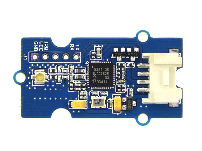
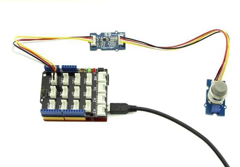
Near Field Communication (NFC) is a set of short-range wireless technologies. It is behind daily applications such as access control system and mobile payment system. Grove NFC features a highly integrated transceiver module PN532 which handles contactless communication at 13.56MHz. You can read and write a 13.56MHz tag with this module or implement point to point data exchange with two NFCs. Grove NFC is designed to use I2C or UART communication protocols, and UART is the default mode. In addition, we assign an independent PCB antenna which can easily stretch out of any enclosure you use, leaving more room for you to design the exterior of your project.

Specifications

  • Working Voltage: 3.3V
  • Working Current:
    • Static Mode: 73mA
    • Write/Read Mode: 83mA
  • Support host interface: I2C, UART(default).
  • Serve for contactless communication at 13.56MHz.
  • Support ISO14443 Type A and Type B protocols.
  • Max operating distance for detecting NFC tags is 28mm depending on current antenna size.
  • Support P2P communication.
  • Dimensions: 25.43mm x 20.35mm
Tip
More details about Grove modules please refer to Grove System

Platforms Supported

ArduinoWioBeagleBoneRaspberry PiLinkIt ONE
Caution
The platforms mentioned above as supported is/are an indication of the module's hardware or theoritical compatibility. We only provide software library or code examples for Arduino platform in most cases. It is not possible to provide software library / demo code for all possible MCU platforms. Hence, users have to write their own software library.

Get Started

  1. Download PN532 library and put 4 folders(PN532, PN532_SPI, PN532_I2C and PN532_HSU) into Arduino’s libraries.
  2. Download [1], put it into Arduino’s library and rename it to NDEF.
  3. Open Arduino IDE. If Arduino IDE is already opened, restart it.
  4. In Arduino IDE, click menus: File -> Example -> NDEF -> ReadTag
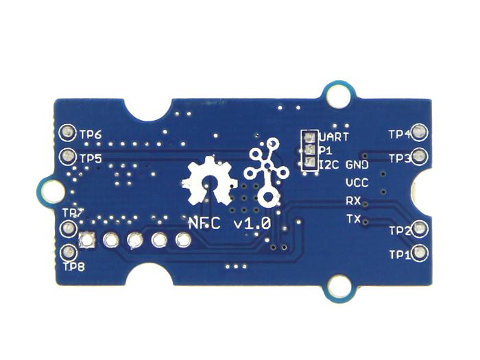
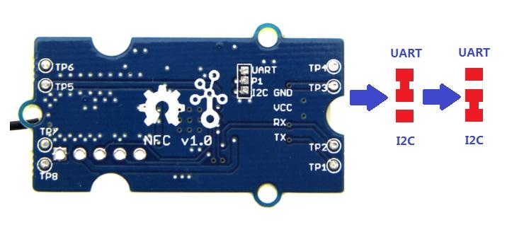
  5. We used I2C interface in the libraries of NDEF, so please cut off the connection between P1 and UART via a little knife, and solder P1 and I2C together.
Caution
Debug for Grove - NFC v1.0 : There is a bug while using I2C communication, please use jumper wires to follow those connection
Arduino/Arduino MegaGrove - NFC
SCLRX
SDATX
GNDGND
5VVCC
You can still use UART interface without cutting any connection, Seeeduino Mega(Arduino Mega) or Seeeduino lite(Arduino Leonardo) are preferred. Following is the modified program.
#include "PN532_HSU.h" #include "PN532.h" #include "NfcAdapter.h"   PN532_HSU interface(Serial1); NfcAdapter nfc = NfcAdapter(interface);   void setup(void) { Serial.begin(115200); Serial.println("NDEF Reader"); nfc.begin(); }   void loop(void) { Serial.println("\nScan a NFC tag\n"); if (nfc.tagPresent()) { NfcTag tag = nfc.read(); tag.print(); } delay(5000); }
Note
If using it with Seeeduino or Arduino UNO, the only way to get the return message is setting it to I2C interface bus. While using it with Mega or Leonardo, you can use UART interface bus. Ensure PN532 library and Don's NDEF libraries are downloaded for Arduino library. And you might test the example ReadTag.ino under folder example. Delete code Line 1 to Line 10 (line \#else ...... and the above lines to top).
Cut following connections:
  • TP1 to UART
  • TP2 to RX
  • TP3 to TX
Solder following connections:
  • TP1 to I2C
  • TP2 to SCL
  • TP3 to SDA

Resources

Help us make it better

Thank you for choosing Seeed. A couple of months ago we initiated a project to improve our documentation system. What you are looking at now is the first edition of the new documentation system. Comparing to the old one, here is the progresses that we made:
  • Replaced the old documentation system with a new one that was developed from Mkdocs, a more widely used and cooler tool to develop documentation system.
  • Integrated the documentation system with our official website, now you can go to Bazaar and other section like Forum and Community more conveniently.
  • Reviewed and rewrote documents for hundreds of products for the system’s first edition, and will continue migrate documents from old wiki to the new one.
An easy-to-use instruction is as important as the product itself. We are expecting this new system will improve your experience when using Seeed’s products. However since this is the first edition, there are still many things need to improve, if you have any suggestions or findings, you are most welcome to submit the amended version as our contributor or give us suggestions in the survey below, Please don’t forget to leave your email address so that we can reply.
Happy hacking

Grove - I2C ADC


Grove - I2C ADC

Introduction

3.3V 5.0V I2C
Grove - I2C ADC is a 12-bit precision ADC module based on ADC121C021. It helps you increase the accuracy of value collected from analog sensor by providing a constant reference voltage. Because its address is changeable, you can use up to 9 I2C ADC at the same time at most. At the other hand, this module provides auto sleep function which lowers the power consumption considerably.

Features

  • Low power consumption
  • High precision
  • Automatic power-down mode
  • Address changeable
Tip
More details about Grove modules please refer to Grove System

Specifications

ItemTypicalUnit
Working Voltage5.0VDC
Resolution12Bit
Sample Rate188.9ksps
Dimension40X20mm

Platforms Supported

ArduinoWioBeagleBoneRaspberry PiLinkIt ONE
Caution
The platforms mentioned above as supported is/are an indication of the module's hardware or theoritical compatibility. We only provide software library or code examples for Arduino platform in most cases. It is not possible to provide software library / demo code for all possible MCU platforms. Hence, users have to write their own software library.

Hardware Overview

J1: used to connect Arduino IIC Interface as Grove - I2C ADC output interface.
J2: used to connect analog sensor as Grove - I2C ADC input interface.
U1: ADC121C021 IC,12-Bit Analog-to-Digital Converter
The black line area is used to set the IIC address. ADDR0 and ADDR1 are shipped connected to L. You can change them to “H” or floating by a little modification on the board(floating is neither connecting “H” nor connecting “L”). Find details in the Reference.

Getting Started

With Arduino

Grove - I2C ADC has two interfaces: input socket(J2) and output socket(J1). Connect an analog sensor to its input socket and connect the I2C ADC to Arduino/Seeeduino also via Grove cables.
Take Grove - Gas Sensor as an example, and now we learn how to read sensor data using Grove - I2C ADC. The hardware installation should be like this:
Now you can read the gas sensor value using the code below.
#include <Wire.h>   #define ADDR_ADC121 0x55   #define V_REF 3.00   #define REG_ADDR_RESULT 0x00 #define REG_ADDR_ALERT 0x01 #define REG_ADDR_CONFIG 0x02 #define REG_ADDR_LIMITL 0x03 #define REG_ADDR_LIMITH 0x04 #define REG_ADDR_HYST 0x05 #define REG_ADDR_CONVL 0x06 #define REG_ADDR_CONVH 0x07   unsigned int getData; float analogVal=0; // convert void init_adc() { Wire.beginTransmission(ADDR_ADC121); // transmit to device Wire.write(REG_ADDR_CONFIG); // Configuration Register Wire.write(0x20); Wire.endTransmission(); }   void read_adc() //unsigned int *data {     Wire.beginTransmission(ADDR_ADC121); // transmit to device Wire.write(REG_ADDR_RESULT); // get result Wire.endTransmission();   Wire.requestFrom(ADDR_ADC121, 2); // request 2byte from device delay(1); if(Wire.available()<=2) { getData = (Wire.read()&0x0f)<<8; getData |= Wire.read(); } Serial.print("getData:"); Serial.println(getData); delay(5); Serial.print("The analog value is:"); Serial.print(getData*V_REF*2/4096); Serial.println("V"); } void setup() { Serial.begin(9600); Wire.begin(); init_adc(); }   void loop() { read_adc();//adcRead); delay(50); }
In the code above, we defined the Vref as 3.0V which is decided by the I2C ADC module. This reference voltage is more accurate than one generated by microcontroller. And you can make that more accurate by measuring the voltage between VA and GND and use that value to replace 3.00 in the code above.
Now you can upload the code.
Afterwards, open the serial monitor and read the values:
Note
The address of Grove - I2C ADC is changeable which means you can redefine its address. That requires some hardware modification on the board. If you are thinking about using more than one I2C ADCs at the same time, follow the instructions in the Reference part below to do so. The maximum number of I2C ADCs that can be used simultaneously is 9, but there are only 4 I2C sockets on Grove - Base Shield V1.2, so if you want to use more than 4 I2C ADC, take a Grove - I2C Hub to create more I2C sockets.

With Beaglebone Green

To begin editing programs that live on BBG, you can use the Cloud9 IDE. As a simple exercise to become familiar with Cloud9 IDE, creating a simple application to blink one of the 4 user programmable LEDs on the BeagleBone is a good start.
If this is your first time to use Cloud9 IDE, please follow this link.
Step1: Set the Grove - UART socket as a Grove - GPIO Socket, just follow this link.
Step2: Click the “+” in the top-right to create a new file.
Step3: Copy and paste the following code into the new tab
from Adafruit_I2C import Adafruit_I2C import time   ADDR_ADC121 = 0x50   REG_ADDR_RESULT = 0x00 REG_ADDR_ALERT = 0x01 REG_ADDR_CONFIG = 0x02 REG_ADDR_LIMITL = 0x03 REG_ADDR_LIMITH = 0x04 REG_ADDR_HYST = 0x05 REG_ADDR_CONVL = 0x06 REG_ADDR_CONVH = 0x07   i2c = Adafruit_I2C(ADDR_ADC121)   class I2cAdc: def __init__(self): i2c.write8(REG_ADDR_CONFIG, 0x20)   def read_adc(self): "Read ADC data 0-4095." data_list = i2c.readList(REG_ADDR_RESULT, 2) #print 'data list', data_list data = ((data_list[0] & 0x0f) << 8 | data_list[1]) & 0xfff return data   if __name__ == '__main__': # Connect the Grove - I2C ADC to I2C Grove port of Beaglebone Green. adc = I2cAdc() while True: print 'sensor value ', adc.read_adc() time.sleep(.2)
Step4: Save the file by clicking the disk icon and giving the file a name with the .py extension.
Step5: Connect Grove I2C ADC to Grove I2C socket on BBG.
Step6: Run the code. You’ll find that the terminal outputs AD value every 2 seconds.

Reference

I2C Address Setting

The ADC I2C has a seven-bit hardware address which is decided by ADR0 and ADR1. ADR0 and ADR1 are connected to L inside the board as default. But you can change it. For example, use a knife to cut off the connection between L and ADR0(as the picture shown below), then you make the state of ADR0 into Floating(connected to nothing). And if you solder up ADR0 and H this time, then you make the value of ADR0 H.
You can find the relationship of hardware I2C address and the values of ADR0 and ADR1 in the following table.
Slave Address[A6 - A0]ADR0 and ADR1 inputs state
ADR1ADR0
1010000(0x50)FloatingFloating
1010001(0x51)FloatingL
1010010(0x52)FloatingH
1010100(0x54)LFloating
1010101(default 0x55)LL
1010110(0x56)LH
1011000(0x58)HFloating
1011001(0x59)HL
1011010(0x5A)HH

How much does the I2C ADC increase the accuracy?

Here is an experiment we make to give you a sense about how much the I2C ADC increase the accuracy of an analog sensor. First, let’s check the values collected directly through analog port on Arduino/Seeeduino from an Grove - Gas Sensor(MQ5)
We upload the code below to get the data.
/* * Grove - Gas Sensor(MQ5) * * The Gas Sensor detect the related Gas density, * Arduino get the result by analogread. the gas Density is * 0~1, larger the output is, the denser the gas. * Connect the Sensor to A0 in this demo; * * By: http://www.seeedstudio.com */ #define Vref 4.95 void setup() { Serial.begin(9600); } void loop() { float vol; int sensorValue = analogRead(A0); vol=(float)sensorValue/1023*Vref; Serial.print("The sensorValue is "); Serial.println(sensorValue); Serial.print("The analog value is "); Serial.print(vol); Serial.println("V"); delay(100); }
The result is:
As default, Vref is generated by Arduino which is theoretically 5V. But actually that is a value afloat which results the deviation of the final data. This kind of inaccuracy is avoided when using Grove - I2C ADC, because it provides a strict 3.0V as Vref. To contrast, in the same condition, sensor values collected by the circuit with Grove - I2C ADC in the scope is shown below:
In order to find out which result is more close to the actual condition, here we use a multimeter to measure the voltage between the pin SIG and pin GND of the sensor.

Resources

Help us make it better

Thank you for choosing Seeed. A couple of months ago we initiated a project to improve our documentation system. What you are looking at now is the first edition of the new documentation system. Comparing to the old one, here is the progresses that we made:
  • Replaced the old documentation system with a new one that was developed from Mkdocs, a more widely used and cooler tool to develop documentation system.
  • Integrated the documentation system with our official website, now you can go to Bazaar and other section like Forum and Community more conveniently.
  • Reviewed and rewrote documents for hundreds of products for the system’s first edition, and will continue migrate documents from old wiki to the new one.
An easy-to-use instruction is as important as the product itself. We are expecting this new system will improve your experience when using Seeed’s products. However since this is the first edition, there are still many things need to improve, if you have any suggestions or findings, you are most welcome to submit the amended version as our contributor or give us suggestions in the survey below, Please don’t forget to leave your email address so that we can reply.
Happy hacking

Grove - Communication


Grove - 4-Digit Display


Grove - 4-Digit Display

Introduction

3.3V 5.0V Digital
Grove - 4-Digit Display module is a 12-pin module. In this module, we utilise a TM1637 to scale down the number of controlling pins to 2. That is to say, it controls both the content and the luminance via only 2 digital pins of Arduino or Seeeduino. For projects that require alpha-numeric display, this can be a nice choice.

Features

  • 4 digit red alpha-numeric display
  • Grove compatible interface (3.3V/5V)
  • 8 adjustable luminance levels
Tip
More details about Grove modules please refer to Grove System

Application Ideas

  • Time display
  • Stopwatch
  • Sensors’ input display

Specifications

ItemMinTypicalMaxUnit
Voltage3.35.05.5VDC
Current0.22780mA
Dimensions42x24x14mm
Net Weight7±1g

Platforms Supported

ArduinoWioBeagleBoneRaspberry PiLinkIt ONE
Caution
The platforms mentioned above as supported is/are an indication of the module's hardware or theoritical compatibility. We only provide software library or code examples for Arduino platform in most cases. It is not possible to provide software library / demo code for all possible MCU platforms. Hence, users have to write their own software library.

Hardware Overview

Grove interface - Can be connected to digital port on Grove - Base Shield.
4 - digit display - Common anode digital tube.
Pin definition: CLK DIO VCC GND

Getting Started

With TI LaunchPad

Displaying the Numbers (4-Digital-Display)
This example demonstrates how to display some digital numbers using a Grove-4-Digital Display.
/* * TM1637.cpp * A library for the 4 digit display */ #include "TM1637.h" #define CLK 39 //pins definitions for TM1637 and can be changed to other ports #define DIO 38 TM1637 tm1637(CLK,DIO); void setup() { tm1637.init(); tm1637.set(BRIGHT_TYPICAL);//BRIGHT_TYPICAL = 2,BRIGHT_DARKEST = 0,BRIGHTEST = 7; } void loop() { int8_t NumTab[] = {0,1,2,3,4,5,6,7,8,9,10,11,12,13,14,15};//0~9,A,b,C,d,E,F int8_t ListDisp[4]; unsigned char i = 0; unsigned char count = 0; delay(150); while(1) { i = count; count ++; if(count == sizeof(NumTab)) count = 0; for(unsigned char BitSelect = 0;BitSelect < 4;BitSelect ++) { ListDisp[BitSelect] = NumTab[i]; i ++; if(i == sizeof(NumTab)) i = 0; } tm1637.display(0,ListDisp[0]); tm1637.display(1,ListDisp[1]); tm1637.display(2,ListDisp[2]); tm1637.display(3,ListDisp[3]); delay(300); } }

With Arduino

The module uses an LED drive chip - TM1637 to control the contents and change the luminance. Here we drive it to display time.
  1. Connect the Grove socket marked “IN” on the LED Strip Driver and digital port 2 of the Grove - Base Shield with a Grove cable. You can change to the digital port as you like. But don’t forget to change the port number in the definition of the demo code at the same time.
  2. Plug onto Arduino/Seeeduino or plug Grove - Mega Shield onto Arduino Mega.
    Seeeduino and Grove - 4-digit display:
    Arduino Mega and Grove - 4-digit display:
  3. Connect Arduino/Seeeduino to PC via a USB cable.
  4. Download the 4-Digit Display library and TimerOne library. Unzip and put them in the libraries file of Arduino IDE by the path: ..\arduino-1.0\libraries.
  5. Restart the Arduino IDE, open one demo code you like, for example ClockDisplay directly by the path:File -> Example ->DigitalTube->ClockDisplay.
  6. Upload the demo code and the clock will be ticking in a few seconds.
    You can see this:

With Raspberry Pi

1.You should have got a raspberry pi and a grovepi or grovepi+.
2.You should have completed configuring the development enviroment, otherwise follow here.
3.Connection
  • Plug the sensor to grovepi socket D5 by using a grove cable.
4.Navigate to the demos’ directory:
cd yourpath/GrovePi/Software/Python/
  • To see the code
nano grove_4_digit_display.py # "Ctrl+x" to exit #
import time import grovepi # Connect the Grove 4 Digit Display to digital port D5 # CLK,DIO,VCC,GND display = 5 grovepi.pinMode(display,"OUTPUT") # If you have an analog sensor connect it to A0 so you can monitor it below sensor = 0 grovepi.pinMode(sensor,"INPUT") time.sleep(.5) # 4 Digit Display methods # grovepi.fourDigit_init(pin) # grovepi.fourDigit_number(pin,value,leading_zero) # grovepi.fourDigit_brightness(pin,brightness) # grovepi.fourDigit_digit(pin,segment,value) # grovepi.fourDigit_segment(pin,segment,leds) # grovepi.fourDigit_score(pin,left,right) # grovepi.fourDigit_monitor(pin,analog,duration) # grovepi.fourDigit_on(pin) # grovepi.fourDigit_off(pin) while True: try: print "Test 1) Initialise" grovepi.fourDigit_init(display) time.sleep(.5) print "Test 2) Set brightness" for i in range(0,8): grovepi.fourDigit_brightness(display,i) time.sleep(.2) time.sleep(.3) # set to lowest brightness level grovepi.fourDigit_brightness(display,0) time.sleep(.5) print "Test 3) Set number without leading zeros" leading_zero = 0 grovepi.fourDigit_number(display,1,leading_zero) time.sleep(.5) grovepi.fourDigit_number(display,12,leading_zero) time.sleep(.5) grovepi.fourDigit_number(display,123,leading_zero) time.sleep(.5) grovepi.fourDigit_number(display,1234,leading_zero) time.sleep(.5) print "Test 4) Set number with leading zeros" leading_zero = 1 grovepi.fourDigit_number(display,5,leading_zero) time.sleep(.5) grovepi.fourDigit_number(display,56,leading_zero) time.sleep(.5) grovepi.fourDigit_number(display,567,leading_zero) time.sleep(.5) grovepi.fourDigit_number(display,5678,leading_zero) time.sleep(.5) print "Test 5) Set individual digit" grovepi.fourDigit_digit(display,0,2) grovepi.fourDigit_digit(display,1,6) grovepi.fourDigit_digit(display,2,9) grovepi.fourDigit_digit(display,3,15) # 15 = F time.sleep(.5) print "Test 6) Set individual segment" grovepi.fourDigit_segment(display,0,118) # 118 = H grovepi.fourDigit_segment(display,1,121) # 121 = E grovepi.fourDigit_segment(display,2,118) # 118 = H grovepi.fourDigit_segment(display,3,121) # 121 = E time.sleep(.5) grovepi.fourDigit_segment(display,0,57) # 57 = C grovepi.fourDigit_segment(display,1,63) # 63 = O grovepi.fourDigit_segment(display,2,63) # 63 = O grovepi.fourDigit_segment(display,3,56) # 56 = L time.sleep(.5) print "Test 7) Set score" grovepi.fourDigit_score(display,0,0) time.sleep(.2) grovepi.fourDigit_score(display,1,0) time.sleep(.2) grovepi.fourDigit_score(display,1,1) time.sleep(.2) grovepi.fourDigit_score(display,1,2) time.sleep(.2) grovepi.fourDigit_score(display,1,3) time.sleep(.2) grovepi.fourDigit_score(display,1,4) time.sleep(.2) grovepi.fourDigit_score(display,1,5) time.sleep(.5) print "Test 8) Set time" grovepi.fourDigit_score(display,12,59) time.sleep(.5) print "Test 9) Monitor analog pin" seconds = 10 grovepi.fourDigit_monitor(display,sensor,seconds) time.sleep(.5) print "Test 10) Switch all on" grovepi.fourDigit_on(display) time.sleep(.5) print "Test 11) Switch all off" grovepi.fourDigit_off(display) time.sleep(.5) except KeyboardInterrupt: grovepi.fourDigit_off(display) break except IOError: print "Error"
5.Run the demo.
sudo python grove_4_digit_display.py
6.This demo may not work if your grovepi doesn’t have the newest firmware, update the firmware.
cd yourpath/GrovePi/Firmware sudo ./firmware_update.sh

Project

Inspired by OVERWATCH, we have made a very cool Wooden Laser Gun toy for fun these day!
The Wooden Laser Gun and the Gun Target are all based on an Arduino board called Seeeduino Lotus. The laser emitter on the Laser Gun is controlled to fire laser pulse to “activate” the Gun Target. And there are 3 light sensors on the Gun Target to detect the laser pulse. It seems very simple right? If you are interested in our project, please make one for yourself or your child! It’s worth to spend one day DIY it as a Xmas present.

Resources

Help us make it better

Thank you for choosing Seeed. A couple of months ago we initiated a project to improve our documentation system. What you are looking at now is the first edition of the new documentation system. Comparing to the old one, here is the progresses that we made:
  • Replaced the old documentation system with a new one that was developed from Mkdocs, a more widely used and cooler tool to develop documentation system.
  • Integrated the documentation system with our official website, now you can go to Bazaar and other section like Forum and Community more conveniently.
  • Reviewed and rewrote documents for hundreds of products for the system’s first edition, and will continue migrate documents from old wiki to the new one.
An easy-to-use instruction is as important as the product itself. We are expecting this new system will improve your experience when using Seeed’s products. However since this is the first edition, there are still many things need to improve, if you have any suggestions or findings, you are most welcome to submit the amended version as our contributor or give us suggestions in the survey below, Please don’t forget to leave your email address so that we can reply.
Happy hacking