2017년 6월 10일 토요일

How to connect App Inventor apps to Arduino using Bluetooth wireless


How to Connect App Inventor apps to Arduino Using Bluetooth

Bluetooth is a low power, short range wireless technology built in to many phones, tablets and other devices.
MIT App Inventor 2 supports a set of Bluetooth communication functions that may be used to send data between smart phones and tablets (see previous tutorials: Part 1Part 2)
This capability may be extended so that App Inventor apps can communicate with Arduino-based devices and other embedded systems.
This tutorial describes how to interface App Inventor apps running on Android to Arduino devices, via the Bluetooth wireless link.

What is Bluetooth?

Bluetooth is an industry standard for low power, short range wireless communications between devices such as personal computers, printers, smart phones, tablets, wireless headphones, wireless stereo speakers, sensor systems (like in security alarms) and other applications.
To learn more about Bluetooth technology (and why it has a funny name!), please read our first tutorial on Bluetooth.

What is Arduino?

Arduino is an open hardware, open software platform for building small electronic devices. The Arduino board is a “microcontroller” – that is, a complete – albeit small, inexpensive and with limited function – computer. Arduino is a popular choice for do-it-yourself projects and is well established in the “Maker” community of DIY project builders. (Side note: I will be at the San Francisco Maker Faire on Saturday, May 16th, 2015).
This is not a tutorial about Arduino boards, software or electronics and presumes the reader is familiar with Arduino development. To learn more about Arduino (and you should learn more about it!) start at the Arduino web site.
This tutorial assumes you have the Arduino software development environment installed on your computer and are familiar with Arduino development.

HARDWARE: Setting Up Arduino for Bluetooth Wireless Communications

There are several versions of the Arduino board; I used the Uno version but others should work just fine.
The Arduino board does not contain Bluetooth hardware – to implement Bluetooth requires using a third-party Bluetooth module. I use the JY-MCU Bluetooth module . IMPORTANT – not all Bluetooth modules will work with App Inventor!  While new versions of Android support all versions of Bluetooth, App Inventor (at the time of this writing) supports “classic” Bluetooth only. In particular, App Inventor does not support the newer Bluetooth LE (Low Energy) version, at least it does not support the Bluetooth LE module that I have.
I can confirm that the JY-MCU Bluetooth module works but the Bluetooth LE modules I have do not work with App Inventor.  My phone can see the Bluetooth LE device but the App Inventor source code cannot communicate with the LE devices.
Where to buy the JY-MCU Module online: Amazon (Prime)Amazon (non-Prime)
The module is also available from other vendors.
Photo shows my Arduino UNO board, at left, a prototyping breadboard with a status LED set up, and the JY-MCU Bluetooth module, just above the breadboard.


Click through to  see how the Arduino and Bluetooth module are setup, and get the Arduino source code and the App Inventor source code!
To learn how to set up this hardware, please refer to this external tutorial from roboTosh on setting up the JY-MCU Bluetooth module with your Arduino board. Be sure to use the sample Arduino source code on that web page to test your hardware set up and verify that everything is working.
The hardware configuration sets up power and interface to the JY-MCU module, and configures a single LED as a status indicator when the code is running.
In the test case (on that page), you’ll program the Arduino using the USB-serial link, and then run the Arduino Serial Monitor to type commands to the Arduino board. Type ‘H’ to turn on the status LED light, and then type ‘L’ (actually anything other than H) to turn the light off.

ARDUINO SOFTWARE: Arduino Source Code for Bluetooth Communications

Once the Arduino and JY-MCU hardware are set up,  install the software on the Arduino board.
You may download the following source code as both a text file (.txt) and as an Arduino .ino project file (see end of this post for download links).
A description of what this Arduino code does and how it works follows the code listing. If you are not familiar with Arduino source code, it is similar to the C++ programming language.
/*
BTArduino sketch By Edward Mitchell http://appinventor.pevest.com
Description:
Uses the JY-MCU Bluetooth module to enable an Arduino board to communicate over Bluetooth
wireless to an Android app written in MIT App Inventor 2, running on an Android device.

Buy the JY-MCU module here
(Amazon Prime) http://www.amazon.com/gp/product/B0093XAV4U/ref=as_li_tl?ie=UTF8&camp=1789&creative=390957&creativeASIN=B0093XAV4U&linkCode=as2&tag=commonsensevi-20&linkId=4L5VQJW7JJKBGCMU
(Amazon non Prime option) http://www.amazon.com/gp/product/B009DZQ4MG/ref=as_li_tl?ie=UTF8&camp=1789&creative=390957&creativeASIN=B009DZQ4MG&linkCode=as2&tag=commonsensevi-20&linkId=S6VEEZVTF4GBGYWC

Credit:
This Arduino code based very loosely on the original Arduino code for the JY-MCU Bluetooth module tutorial at
http://robotosh.blogspot.com/2012/07/arduino-jy-mcu-bluetooth.html

A tutorial for using this code with App Inventor 2, is available at the appinventor.pevest.com
web site. Please refer to the tutorial for information and source code for the Android side of this sketch.

Note - this sample code is intended only to show how the basic Bluetooth communications link may
be set up, and illustrates just one possible way of sending commands from the Android device
to the Arduino phone. The purpose of this code is as an introduction/tutorial and is not meant
to be used for any particular purpose. No warranties.
*/

// Constant Definitions
#define LEDPIN 8 // Pin on Arduino board to which status LED is connected
#define READ_RATE 100 // How often the serial link is read, in milliseconds
#define FLASH_RATE 100 // The on/off period in milliseconds, for the LED Flash status feedback

// Declarations
byte cmd; // Stores the next byte of incoming data, which is a "command" to do something
byte param; // Stores the 2nd byte, which is the command parameter

// Initialization
void setup() {

pinMode(LEDPIN, OUTPUT); // pin 48 (on-board LED) as OUTPUT
digitalWrite(LEDPIN, LOW);
Serial.begin(9600); // start serial communication at 9600bps
}

// Arduino Execution Loop
void loop() {

if ( Serial.available() ) // if data is available to read
{
cmd = Serial.read(); // read it and store it in 'cmd'
// Data format is byte 1 = command, byte 2 = parameter
};

switch ( cmd ) {
case 1:
// First byte contains a generic "command" byte. We arbitrarily defined '1' as the command to then check the 2nd parameter byte
// User can additional commands by adding case 2, 3, 4, etc
{
// read the parameter byte
param = Serial.read();
switch (param)
{
case 1:
// Android device requests the Arduino to send some data back to Android
flashLED(1);
if (Serial)
{
// Send back 2 bytes with a value of 1, 2
Serial.write(1);
Serial.write(2);
};
break;
case 2:
// Turn on status LED
flashLED(2);
digitalWrite(LEDPIN, HIGH );
break;
case 3:
// Turn off status LED
flashLED(3);
digitalWrite(LEDPIN, LOW);
break;
case 4:
// Demonstrate flashing the LED 4 times
flashLED(4);
break;
case 5:
// Demonstrate flashing the LED 5 times
// Could add code here to control a servo via PWM outputs
flashLED(5);
break;
default: break; // do nothing
} // switch (param)
} // switch (cmd) case 1
default: break; // do nothing
} // switch (cmd)

delay(READ_RATE); // wait 100ms for next reading
}

// Support routine
void flashLED (int n) {
// Flash the LED n times, to provide an on board status indicator
for (int i=1; i<=n; i++) {
digitalWrite (LEDPIN, HIGH);
delay (FLASH_RATE);
digitalWrite (LEDPIN, LOW);
delay(FLASH_RATE);
};
return;
}
Description of the Arduino Code
This description assumes you are familiar with Arduino projects.
The basic operation configures a Serial port to communicate with the JY-MCU module. Data is  received or transmitted between the JY-MCU module using the Serial interface.
This project defines a very simple protocol for communicating between the Arduino and the App Inventor app running on an Android device.
The protocol is merely a 2-byte sequence. The first byte contains a value that we interpret as a “command”, and the second byte contains a parameter value for the command. When the code reads incoming data from the JY-MCU module, the first byte is stored in a variable named cmd and the second byte is stored in a variable named param.
The initialization code, in setup() sets the Serial data rate to 9600 bps as this is the default data rate on the JY-MCU module. The module may be configured to use different (and faster) data rates but for this tutorial, the data rate is left at the default value of 9600 bps.
The loop() section of the Arduino code reads an incoming cmd byte value, and then uses a switch statement to select from among a set of possible values. This tutorial implements only a command value of 1; you can add additional values to define additional commands. For a command of 1, the 2nd byte is then read as the parameter value. (One could define a command value of say, 2, and then define that the next several bytes contains a text string, for example.)
Depending on the parameter value (2, 3, 4, etc) a different function may be performed. As defined here, a value of 2 turns on the status LED; a value of 3 turns off the status LED.
A parameter value of 1 tells the Arduino to send 2 bytes of data back to the App Inventor app, via the Bluetooth connection. This could be modified to send back other types of data (2 byte or 4 byte numbers or text strings).
Additionally, the LED flashes the value of the parameter byte. For example, if a parameter value of 4 is received, the LED flashes 4 times, to provide visible feedback.
You can modify this code to implement new functions on the Arduino that are controlled remotely from the App Inventor app. For example, you could define that a parameter value of 4 means to set pin 9 of the Arduino HIGH and a parameter value of 5 means to set pin 9 to LOW. You could also use this to pass control information to operate a PWM interfaced servo or motor.
Finally, flashLED() is a simple function to flash the LED the number of times indicated by its argument.

APP INVENTOR 2 SOFTWARE for Bluetooth

The “Bluetooth Client for Arduino” is based on the similar client code introduced in the part 1 and 2 tutorials on Bluetooth. The app provides a simple interface to connect to the Bluetooth device, to disconnect from the device, to send a numeric value (such as 1, 2, 3, etc) and to display link status and data received from the Arduino.
The blocks code for this app may be downloaded at the link provided at the end of this tutorial.
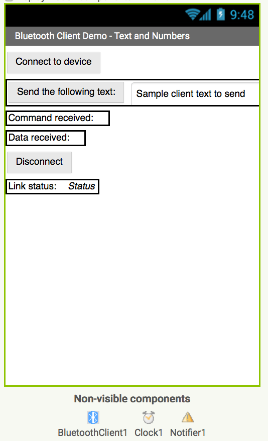
 The Designer View
The user interface has 3 buttons: Connect to device, Disconnect device and Send Numeric.
Labels are used to display status and received data.
The User Interface, as seen in the MIT App Inventor Designer:

The App Inventor App In Operation
FIRST! “Pair” Your Bluetooth Devices!
Prior to running the App, you must go into the Android Settings | Bluetooth options and “pair” the JY-MCU Bluetooth module with your Android phone. With the Arduino and JY-MCU powered up, you should see a device named “HC-06”. Please see the section titled Setting Up A Bluetooth Connection in Part 1: Basic Bluetooth communications using App Inventor. You may need to enter a pairing code of “1234” to set up the HC-6 device. (See  the roboTosh link for details on that.)
Once the app is running, you should see that the link is Disconnected.
Select Connect to device.
The app displays a list of potential Bluetooth devices. Select the HC-06 device from the list. There will be a pause for a second or two as the connection is established.
If you see the following error message when you attempt to connect, it means your Arduino/Bluetooth module is probably not powered up or is too far away:
Once the link is set up, the Link status will display “Client connected”:

Enter a numeric value of 2 and press Send Numeric – the status LED should turn on. To turn it off, enter a value of 3 and press Send Numeric – the status LED should turn off. Note that the LED will also flash a number of times equal to the numeric value sent.


To demonstrate sending data from the Arduino device to the App Inventor app, enter a numeric value of 1 and press Send Numeric. A moment later you should see that the Data received status displays “1,2”:
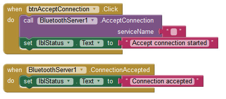
 The Blocks Code

The original Bluetooth client code (see the original Parts 1 and 2) has been simplified to do only what is needed for the Arduino link.
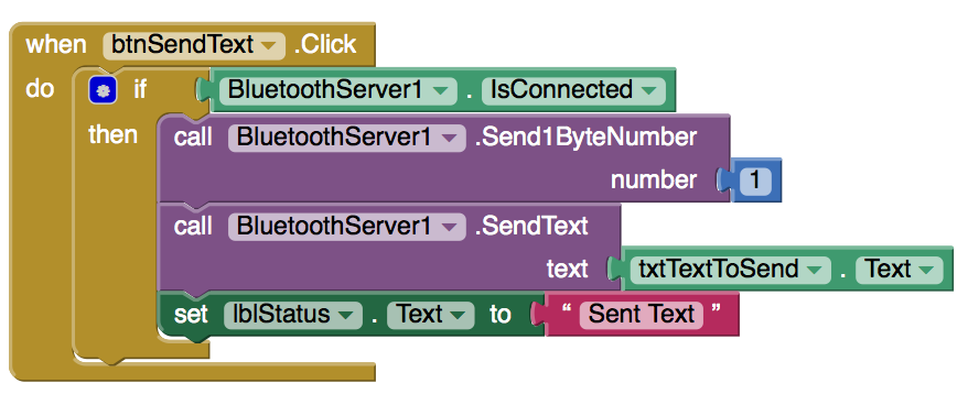
The Send Numeric click event handler sends the numeric value across the Bluetooth link. For simplicity, only positive numbers are permitted (the absolute value function converts negative values to positive values), and since a byte may only represent values between 0 and 255, anything larger is set to 255.
The command byte value of 1 is sent, followed by the numeric value:


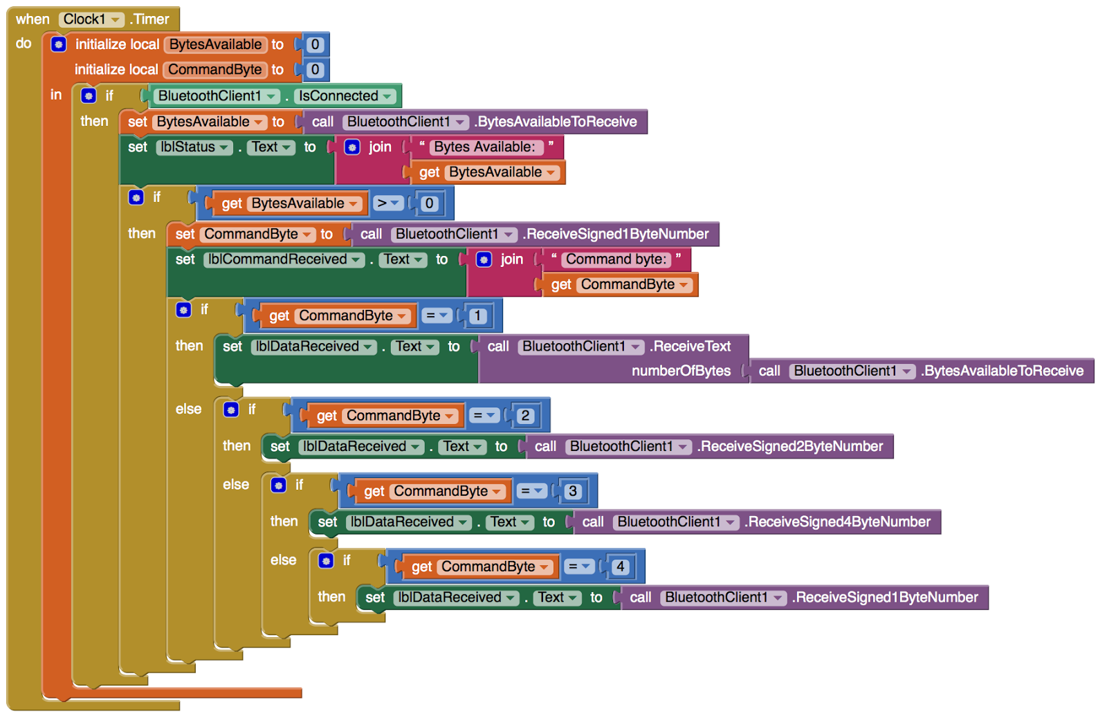
Data is received inside the Click Timer event. The two incoming bytes are read and displayed on the screen:

Key Features Shown

⦁ Setting up the Arduino hardware to demonstrate Bluetooth communications using the JY-MCU module
⦁ Writing and installing Arduino code to use the JY-MCU module for Bluetooth communications
⦁ Writing the blocks code in MIT App Inventor for an app that links to the Arduino device over Bluetooth wireless.
⦁ Operation of sample programs showing how to send and receive data via Bluetooth.

Future Development

The command/parameter protocol may be extended to support many types of data transfer and a greater set of remote control functions.
The communication protocol, in a production system, might be improved to include data error detection. If data bytes are missed or damaged, they should be detected and handled or discarded.

Source Code Downloads

⦁ Arduino source code (in text form): BTArduino_Sketch_Source.txt
⦁ Arduino project file (.ino file) – use your browser’s right-click Save As option: sketch_ArduinoBT.ino
⦁ App Inventor project file (.aia file) – use your browser’s right-click Save As option: sketch_ArduinoBT.ino BTArduino_Client.aia

DISCLAIMER

These code files and instructions are provided solely for educational purposes but you are free to use these in your projects. No warranty of any type is implied. I will  respond to reports of defects in the code but I am unable to debug your hardware or software projects or to develop custom code for you!


Part 2: Sending numeric data using App Inventor Bluetooth communications


Part 1 of this tutorial introduced Bluetooth communications and implemented a simple method of sending text data back and forth between two Android devices over the Bluetooth wireless link. If you are not familiar with using App Inventor’s Bluetooth component, start with Part 1.
In Part 2, a data packet concept is introduced to guide the communications between devices, and is used to send a combination of text and numeric data. This section introduces the concept of binary numbers so that you can understand why we would handle text and numbers in different ways.
This tutorial modifies the user interface of both the client and server programs introduced in Part 1. Then, blocks code is added to send text and numeric data. Numeric data is sent as binary data using special methods of the Bluetooth components.
Related:

Brief Introduction to Binary Numbers

Numeric data is sent in binary format rather than decimal text format (e.g. a number like 237 is in decimal format). With Bluetooth, we need to decide if our numbers are 1-byte, 2-byte or 4-byte numbers – and to understand that, we need to understand a little bit about binary numbers. (This will not hurt – I promise! Or at least it will not hurt very much!)
When we write programs with numbers, we type in numbers like “42”, “9”, and “128”.  But computers do not (normally) store numbers in text form, but instead, convert them into a binary representation. This section gives an introduction to binary numbers and how they are stored, and why this is a factor in Bluetooth communications.

You do not need to know these details to use Bluetooth communications for sending text and numbers – but it is helpful to understand why App Inventor can send several different types of numbers! If you prefer to skip this section, you may do so.
When we write numbers, such as 128, we are writing them in “base 10 notation”. That is because each digit holds a value from 0 to 9 (or ten values). The number 128 is 3 digits stored as:
1 * 100 + 2 * 10 + 8
From the right and the moving to the left, there is a “ones digit”, then a “tens digit”, and then a “hundreds digit”.  Another way to look this is to say we write out numbers similar to:
hundreds     tens      ones
Another way to write the value of the digit positions is:
102     101     10
Let us look at binary notation. In binary, each digit can hold only the values 0 or 1 – we only have 2 values per digit, not ten! Indeed, we say a binary number is stored in base 2 (get it? just 2 values in base 2 whereas base 10 has 10 values per digit). A binary number might look like:
1001
representing a value of 0 or 1 at each digit position. But what does that mean in terms of a number value? It means instead of having position values like 100s, 10s and 1s, we have position values of:
16     8     4     2     1
which corresponds to
24     23     22     21     20
In binary notation, each digit has only the value 0 or 1 (not the 0 to 9 of base 10).  To keep this simple, consider the number 9 (in good old base 10). Writing this in binary, we get the digits:
1001
Remember – each digit position holds only a value of 0 or 1, which is then multiplied by the digit’s place. Just as we multiplied the “1” in 128 by one hundred and the “2” by ten, binary numbers have their own multipliers for each digit’s place. For the above number, the multipliers are:
8     4     2     1
Or
1 * 8 + 0 * 4 + 0 * 2 + 1 * 1
Because we have two values per digit position (0 or 1), we say this is “Base 2” (versus base 10 which had 10 possible values per digit position).
Numbers that we write in text are converted into the binary form for processing on computers [1]. A group of 8 binary digits – also known as 8 bits – is called a byteThe value 1000 0010 represents 8 bits stored in one byte of data.
Depending on the range of values stored, numbers are typically stored as 1-, 2- or 4-byte binary values. A 2-byte number has 16 bits and a 4-byte number as 32 bits.
⦁ 1 byte: for values in the range of 0 to 255, or -128 to +127
⦁ 2 bytes: for values in the range of 0 to 65535 or -32768 to +32767
⦁ 4 bytes: for values in the range of 0 to 4294967295 or -2147483648 to +2147483647
For negative numbers, one of the bits is reserved for the sign of the value which leaves one less bit for the value, as shown above.
Key Point for Bluetooth in App Inventor

App Inventor’s Bluetooth component supports the sending and receiving of binary values. But to use the feature, you need to know the range of values the app will send – and then specify whether the app should use 1-byte, 2-bytes or 4-bytes for the numeric value per the above table.
Floating point or “real” numbers?
The numbers in the preceding example are called “integers” – they do not store a decimal point. How would you represent a value like 3.14159 or 127.35?
Such values are called “real” or “floating point” numbers (because the decimal point can appear at any location). There are several ways computers can store floating point numbers but a description of those details is beyond what we need to understand Bluetooth communications.
Binary Numbers Footnote
[1] There is another type of numeric storage called binary coded decimal or BCD. It is sometimes used in business and accounting applications. BCD numbers store each digit in binary by converting the values 0 to 10 to a 4-bit binary number. A number like “128” would be stored using 3 BCD digits, where each digit is stored in binary, like this:
1        2        8
0001 0010 1000
You do not need to know about BCD to use Bluetooth – this is just to illustrate that there are other ways that numbers may be stored in computing systems.

Designer View: Bluetooth Server and Client Apps

The purpose of this app is to demonstrate the sending of binary numbers (versus just text values). The Server app is modified to send binary numbers and the Client app is modified to receive those numbers.  (Optionally, the Client app could also be modified to send binary numbers and the Server could be modified to receive binary numbers. Both sides can process binary numbers.)
The user interface of the Server Demo app shown in Part 1 is modified as shown below, to send either text or to send numeric data. For the full implementation details, download the source code, at the end of this blog post.
The Client Demo app is slightly modified to present two lines for the incoming data: (1) a display of the incoming command, and (2) the data received (either text or numeric values go here). The purpose of the command value will be explained in the next section.

The Blocks Code

In Part 1 of this series, our sample Bluetooth program sent and received only text messages.
In Part 2, our sample program can send both text and numbers. The sender needs to notify the receiver that the data being sent is either a text value or a number. Specifically, the sender needs to indicate whether the data is text, a 1-byte number, a 2-byte number or a 4-byte number.
The type of the data being sent is included in the data stream as the first byte of data. We call this the command byte (as in “you are commanded to receive one of the following”).
The command byte has one of the following values to indicate the type of data being sent:

Command Bytes
1=text string
2 = 2 byte number
3 = 4 byte number
4 = 1 byte number
The command byte is sent before the data as shown by the blocks in the Send Text button event handler:

Think of the data transmission as a data packet that contains both a command byte and a package of data.
The Send Numeric data button is similar – but a bit more complex!  While we could put all numeric values into a 4-byte value, why send extra bytes if we do not need to?
The event handler looks at the value of the number, determines in which the range the value lies, and then uses the 1-byte, 2-byte- or 4-byte Bluetooth sending methods, as required for the number:

In the Client app, the bulk of the code changes are in the Timer event handler. At each timer “tick”, the app checks to see if data is available over Bluetooth. If data is available, the first byte of the incoming data is read using ReceiveSigned1ByteNumber.  This is the command byte. Depending on the value of the command – 1, 2, 3 or 4 – the appropriate Bluetooth method is used to read the next bytes of data as either a number or as a text value.
The methods ReceivedSigned1ByteNumberReceiveSigned2ByteNumber, and ReceivedSigned4ByteNumber correspond to the 1-byte, 2-byte- and 4-byte binary numeric data types.
Key Features Shown
⦁ Introduction to binary data formats
⦁ The concept of 1-, 2,  and 4-byte numeric values
⦁ The concept of integer and floating point numbers
⦁ Use of the App Inventor Bluetooth features for sending and receiving numeric data
⦁ The concept of the command byte to specify the type of data sent
Downloads
⦁ BTClient2.aia App Inventor source file (App Inventor source code files have the filename extension .aia)
⦁ BTServer2.aia App Inventor source file
⦁ Download the source code to your computer. Then, in App Inventor, go to the Projects menu and select “Import project (.aia) from my computer…”
⦁ Remember – you need two separate Android devices in order to run and test the Bluetooth sample programs!

Part 1: Basic Bluetooth communications using App Inventor


BY EDWARD M · JANUARY 23, 2015
This tutorial covers basic App Inventor Bluetooth communications code.   Subsequent tutorials will add additional features. To implement and test this sample code, you need access to two Android devices – one to act as a Bluetooth “server” and the other to act as a “Bluetooth” client.
I tested this code using an old LG smart phone running Android 2.2 and a new Nexus 5 running Android 5.0.1.  I also tested this code using the Nexus 5 paired with a Nexus 7 tablet.
This tutorial is lengthy – it introduces Bluetooth communications, then presents the user interface and blocks code for both the server and client programs, and then discusses how to set up the Bluetooth Communications link using “pairing”.

Downloadable App Inventor source code for the client and server is at the end of this post.

This is the first of several posts on Bluetooth. This first post covers basic connections and the sending and receiving of text between two Bluetooth devices. The two halves of the link – client and server – are kept in separate apps to keep this simple, however, it is possible for a single app to act as both a client and a server. A subsequent post will show how to send other types of data, such as numbers, and introduce additional features for using Bluetooth communications.
Introduction to Bluetooth
Bluetooth is the communications technology with a funny name.[1] Bluetooth is actually named for a long ago Danish king who worked to unite groups of people, which is similar to Bluetooth’s goal of interconnecting different devices.  The King’s real name was “Harald” but he had a nickname that translates as “Bluetooth” – no one knows for sure why he had this nickname but one thought is he had one dark tooth that may have appeared black or blue. And that is certainly an obscure way to choose a name for new technologies!
Bluetooth establishes a very low power, short range (up to 10 meters) communications link between two devices. Bluetooth uses the same frequency band (2.4 Ghz) as Wi-Fi, but uses different technology. Both Bluetooth and Wi-Fi use forms of spread spectrum radio links that result in signals moving around within a wide band in ways that enable sharing of the spectrum by multiple devices. But the two technologies serve different purposes, are not identical, and cannot communicate with one another.
Bluetooth applications include common wireless headsets for wired and cellular phones, and in-ear cordless adapters for phones. Bluetooth is also used by cordless headphones and to exchange address cards between devices, and for industrial applications where sensors collect and send data into a network.
There are two forms of Bluetooth – classic Bluetooth, which we use in the sample applications, and a newer version known as Bluetooth low energy, Bluetooth BLE, Bluetooth LE or Bluetooth Smart – all referring to the same new technology.  The newest Android devices running Android 4.3 or newer, usually support the newest Bluetooth Smart technology. Regardless, we use classic Bluetooth which is backwards compatible to older phones, and is the technology supported by App Inventor.
Setting up a Bluetooth devices involves “pairing” the two devices and establishing a connection. This will be covered later in this tutorial.
Footnote:
[1] Actually there is another communications technology with a funny name called TWAIN, which is an acronym for “Technology without and interesting name” (really!)

The Designer View

There are two separate apps for Bluetooth communications – one is a “server” app that runs on one device, and the other is a “client” app that runs on a second device.
Bluetooth must be enabled on both devices, and the devices need to be paired before running these apps. (How to do this is explained near the end of this tutorial.)
The server must be run first on one device and then the client app on the 2nd device connects to the server before data can be sent between the two devices. More on this later in this tutorial.
The server user interface is shown here:
The main components of the server interface design are:
⦁ Accept Connection Button – press this to set the server to accept a connection from another device. Connections are not possible until the AcceptConnection service is started.
⦁ Send the following text Button – the text is the following text box is sent to the other Bluetooth device.
⦁ Disconnect Button
⦁ Status messages – Status about the communications link, and any messages received from the other device are shown on the display
⦁ Non-visible components – The apps use a clock to cause activities to occur at a preset interval. The Notifier1 component is used to display error messages (see tutorial on the use of Notifier), and BluetoothServer1 provides the Bluetooth support. The BluetoothClient1 and BluetoothServer1 components are located in the Connectivity section of the Designer palette.
How each of the buttons and components are used to run the program are explained later, in a section on setting up Bluetooth on your devices and running the apps.
The client user interface is shown here:
The user interface is similar to the server except instead of AcceptConnection there is a Connect to device button, and instead of a BluetoothServer1 component, the BluetoothClient1 components is used.
The Connect to device button is actually a ListPicker component and not a standard button.
For both the client and server apps, the TimerInterval of the Clock properties is set to 1000 milliseconds or 1 second. Other small values may also be used. This value determines how frequently to check the Bluetooth link for incoming data from the other device. As shown, each app will check the link once per second.

Blocks Code

Bluetooth Server app
We start with the server app implementation.  The client app is presented after the server app.
The first step is to check that Bluetooth is activated or switched on. If not, an error message is displayed reminding the user to open Android’s Settings and then switch Bluetooth to on.
The Initialize event occurs when the app is launched – and this is a good place to check whether or not Bluetooth is enabled on the device.
Assuming that Bluetooth on the device is currently “on”, the next step is to accept a connection from another device when the btnAcceptConnection button has been pressed. This causes Bluetooth to begin listening for an incoming connection.
Once a connection request has been received and processed, a ConnectionAccepted event occurs. In our basic app, we update the status message on the app screen.
The Timer Event Handles Receiving of Data
Receiving data sent over Bluetooth takes place in the Clock1.Timer event handler. Remember, the clock is set so that the Timer event happens once per second. Every second, the app will check if any data has been received.
To prevent reading data when Bluetooth is not connected (this would cause an error), an if-then statement checks the IsConnected property of BluetoothServer1. This value is set to true when the devices are connected and false if the connection is not currently available.
IsConnected should be true if a connection has been accepted. But because this is a wireless connection, a device might go out of range or be turned off, breaking the connection. It is good programming practice to check that the connection is working before trying to send or receive data.
The property BytesAvailableToReceive tells us how much data is available (one text character is equal to one “byte” of data). If this value is zero, then no data is available. But if the value is greater than zero, then our app may read the incoming data and update the status and messages to the app display.
The Send Text button event handler is similar to the receive code located inside the Timer event except that data is sent using the SendText method to transmit the data to the other device.
The Disconnect button handler is self explanatory!
Error  Handling
One thing to know about wireless communications is that errors happen. For most of our App Inventor apps, we ignore potential errors – if errors occur, the app stops running and Android displays an error messages.
Rather than letting that occur, our app can intercept the error condition by adding an error event handler to the main screen, Screen1. The ErrorOccurred event has four parameter values (local variables) that contain information about the error. The error handler displays the error values on the screen, rather than shutting down the app.

Bluetooth Client App

Now that the server app is complete, we present the client app that runs on the other device. In many ways, the client app is a mirror image of the server, but refers to the BlutoothClient1 component instead of the BluetoothServer1 component.
App Initialization
Same as the server, except it uses BluetoothClient1.
Connecting
When the two devices are running, the server app is set up first to accept connections. Then, on the client side, the user selects the Connect ListPicker button and selects the device name from a list of available Bluetooth devices.  Because the list of devices is in the form of a list, the ListPicker is a great interface component to display the device list and handle the selection. (See my earlier tutorial on ListPicker.)
Before the list is displayed, the list is filled with the list of Bluetooth devices (AddressesAndNames). The set lblStatus.Text block may be deleted as it was used during my testing and is not needed in the final version of the client.
After the device has been selected with the ListPicker user interface, the Connect method of BluetoothClient1 establishes the connection. The method returns a value of true if the connection was successful; in which case a message is sent to the server app.
Disconnect is self explanatory.
Receiving Data
Like with the server, the reception of data is implemented using a timer. Once per second, the client checks to see if data is available, and if it is, reads and displays the data on the app display.
While the server must be running prior to the client making a connection, once the two devices are connected, either app can send data to the other app, at any time.
Error Handling
The client’s error handling is identical to the server’s error handling.
Setting Up A Bluetooth Connection
Before you use the Bluetooth communications apps, do the following:
1. Use Build .apk or other method to obtain the server app, download and install on your first Android device.
2. Use Build .apk or other method to obtain the client app, download and install on your second Android device.
3. Go in to the Android Settings and turn on the Bluetooth feature.   The user interface for the Bluetooth configuration varies slightly depending on which version of Android you have.  On 2.2, for example, you need to select Wireless & Networks, and then choose Bluetooth, while on Android 5.0, Bluetooth appears in the topmost Settings menu.
4. In newer versions of Android, when the Bluetooth Settings menu is active, your device is broadcasting its availability to other nearby devices. On older versions, you may need to click an option to make your device “discoverable”. (Note – my Nexus 5 is not visible on my very old LG 2.2 device – however, the Nexus 5 sees the LG and the two can be connected from the Nexus 5 side).
5. Once your two devices see each other over Bluetooth, you may be prompted to “pair” the devices, or (depending on Android version), you may have to manually choose the device and then choose pairing. Follow the on screen instructions.
6. Once the two devices are “paired”, launch the Server app and select Accept Connection.
7. On the other device, launch the Client app and select Connect. If all goes well, you should see a “client connected” message on the Server app.

Key Features Shown
⦁ Introduction to Bluetooth wireless
⦁ User interface for a Bluetooth server and client app
⦁ Use of the Bluetooth Server and Client components to set up a link
⦁ Use of error handling
⦁ Setting up devices for Bluetooth communications
⦁ More features in future tutorials!
Downloads
⦁ BTClient1.aia App Inventor source file (App Inventor source code files have the filename extension .aia)
⦁ BTServer1.aia App Inventor source file
⦁ Download the source code to your computer. Then, in App Inventor, go to the Projects menu and select “Import project (.aia) from my computer…”