Difficulty: 6 (1 for easiest to 10 for hardest)
Time: 3 hours
Parts list / prices:
⦁ RGB LED (common cathode) $1~2
⦁ Jump wire: $2.5~4
⦁ 400 holes breadboard ($4~10 USD)
⦁ PC which can un Arduino IDE(OS can be Windows, MAC OSX or any distribution of Linux), App Inventor is executed in your browser.
Introduction
This tutorial will teach you how to control a RGB LED on an Arduino 101 board with an Android device. We used App Inventor to make the Android app because it is graphical (just like Scratch) and you can easily build an .apk installation file for almost any Android device. For who have no Android devices in their schools, App Inventor has an emulator for basic usage as well (hardware-related functions like sensors and Bluetooth is not available on the emulator).
After this tutorial, you can attach more RGB LEDs or other display modules to achieve more astonishing effects. Try to build your own Philip HUE light bulb!
Note: This tutorial uses the Arduino 101 board for its onboard BLE communication ability. If you are using an earlier Bluetooth module like HC05 or HC06, you should use App Inventor’s BluetoothClient instead of the BluetoothLE component in this tutorial.
Arduino Source code
Let’s start
This section will tell you how to get the pixel’s RGB intensity of where you touched, then send these data to the Arduino 101 to control an attached RGB LED.
Hardware
Use a RGB LED (common cathode). Please attach its R G B terminals to the Arduino 101’s pins 9, 6 and 3 (~PWM of course), as shown below. If yours is a common anode, please refer to its data sheet and modify the circuit.
Software
The software for this app is divided into App Inventor and Arduino 101. Please see the separate sections below:
App Inventor
Designer
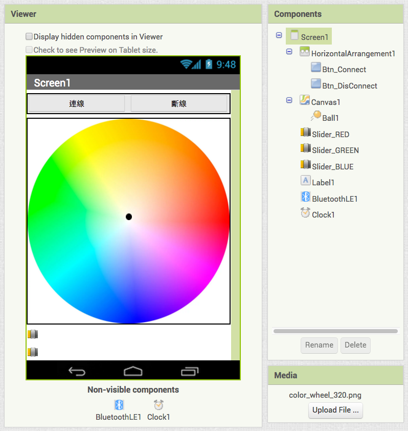
Please add the components below to your project. The numbers in parentheses designate how many of each you have to add. For example, Button(2) means there are two button components in your project. You don’t have to rename the component as we did, but for better readability we suggest you to rename components of the same type with different names.
Canvas(1): get touch point’s coordinates for RGB color intensity.
Button(2):
⦁ Btn_Connect: Ask BluetoothLE component to connect with specified BLE device when clicked.
⦁ Btn_DisConnect: Ask BluetoothLE component to disconnect with specified BLE device when clicked.
Sliders(3): Three sliders to represent the RGB value of touch point.
BluetoothLE(1): Send/receive data through Bluetooth Low Energy protocol.
Clock(1): Ask BluetoothLE component to send data to Arduino 101 periodically.
Blocks
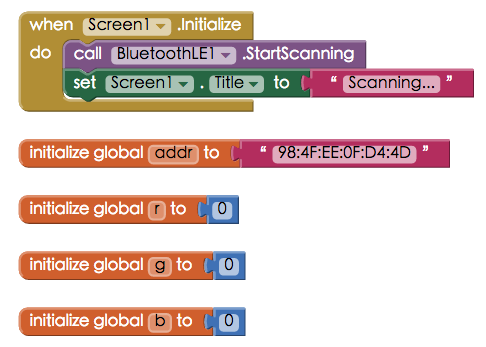
1. Initialize
Declare variables. addr is the BLE device (Arduino 101)’s hardware address, which is labeled on the back of your Arduino 101. r, g and b are numerical variables to used to save the RGB value of the touch point.
When your app initializes (Screen1.Initialize event), we ask the BluetoothLE component to StartScanning for available BLE devices and show related messages on Screen1.Title.
2. Connect / Disconnect
When Btn_Connect is clicked, we ask the BluetoothLE component to connect with the specified BLE device (addr variable). Then set Btn_DisConnect to be enabled and Btn_Connect to be disabled. The reason here is simple: you can not disconnect when you have nothing connected, and vice versa. Finally show “Connected” message on the screen title.
On the other hand, when Btn_DisConnect is clicked, we ask BluetoothLE component to disconnect and set the two buttons to their original state for another connection.
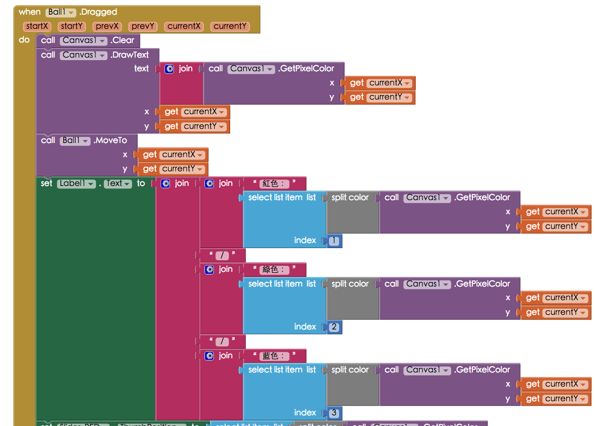
3. Drag your finger to get the RGB or value of the touch point
In the Ball.Dragged event, when this ball is dragged (meaning your fingertip’s location), the following will happen:
A. Clear canvas.
B. Use GetPixelColor to show the color intensity of that touch point where you touched the canvas. This value is a quite big negative integer; in step D we will extract the real color value from this integer.
C. Move the Ball to where we’ve touched.
D. Use select list item with split to get the Red, Green and Blue value of where the user has touched, then show the information on Label1. Use select list item and split color to extract its item #1, #2 and #3, then show the final R G B values on Label1.
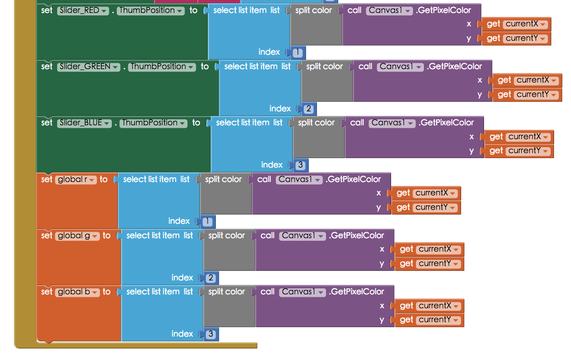
4. Update slider
Next, still in the Ball.Dragged event, we will update every Slider’s thumbPosition and r, g, b variables’ values to the canvas location’s color intensity where user has touched. We are now ready to send data to the Arduino 101!
If you feel that the code here is too tedious, you can make it into a procedure, which can make your screen more simplified and readable.
5. Send data back to App Inventor
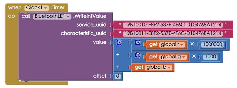
The Clock1 component will activate the Clock.Timer event every second, which will first combine the red, green and blue values of the touch point together, then send the combined result by BluetoothLE.WriteIntValue. For example (128, 34, 255) will combine as 128034255. The Arduino will separate them back into three independent integers. You can modify the TimerInterval value of Clock1 component in case to achieve a better operation experience.
Arduino 101
First, in the setup() function, a special library is included: <CurieBLE.h>(line 1), which is specially designed for Arduino 101’s Intel Curie chip. We’ve prepared all the settings for BLE (lines 2~31). As for the UUID, you can use websites like UUID generator (https://www.uuidgenerator.net/) to create your own UUID. Please notice that the UUID of service and characteristics are one-digit different.
In the loop() function,
Within the if (LEDStatus.written()) condition from line 53 to 67, we use incom = LEDStatus.value(); to get the integer value sent from App Inventor. Arduino will separate this integer into 3 separate integers representing the RGB LED’s light intensity. Finally we use analogWrite() to control corresponding pins(line 63~65).
01
|
#include <CurieBLE.h>
|
02
|
#include <stdlib.h>
|
03
|
#define LEDr 9
|
04
|
#define LEDg 6
|
05
|
#define LEDb 3
|
06
|
|
07
|
BLEPeripheral blePeripheral;
|
08
|
//BLE Peripheral Device (the board you're programming)
|
09
|
BLEService ControlLED("19B10010-E8F2-537E-4F6C-D104768A1214");
|
10
|
//initialize a BLE Service
|
11
|
|
12
|
// BLE LED Switch Characteristic - custom 128-bit UUID, read and writable by central
|
13
|
BLEUnsignedIntCharacteristic LEDStatus("19B10011-E8F2-537E-4F6C-
|
14
|
D104768A1214", BLERead | BLEWrite );
|
15
|
|
16
|
int incom = 0;
|
17
|
int r, g, b ;
|
18
|
|
19
|
void setup() {
|
20
|
Serial.begin(9600);
|
21
|
|
22
|
// set advertised local name and service UUID:
|
23
|
blePeripheral.setLocalName("ControlLED");
|
24
|
blePeripheral.setAdvertisedServiceUuid(ControlLED.uuid());
|
25
|
|
26
|
// add service and characteristic:
|
27
|
blePeripheral.addAttribute(ControlLED);
|
28
|
blePeripheral.addAttribute(LEDStatus);
|
29
|
|
30
|
// begin advertising BLE Light service:
|
31
|
blePeripheral.begin();
|
32
|
|
33
|
Serial.println("BLE RGBLED control.");
|
34
|
|
35
|
// set Light pin to output mode
|
36
|
pinMode(LEDr, OUTPUT);
|
37
|
pinMode(LEDg, OUTPUT);
|
38
|
pinMode(LEDb, OUTPUT);
|
39
|
}
|
40
|
|
41
|
void loop() {
|
42
|
// listen for BLE peripherals to connect:
|
43
|
BLECentral central = blePeripheral.central();
|
44
|
// if a central is connected to peripheral:
|
45
|
if (central) {
|
46
|
Serial.print("Connected to central: ");
|
47
|
// print the central's MAC address:
|
48
|
Serial.println(central.address());
|
49
|
|
50
|
// while the central is still connected to peripheral:
|
51
|
while (central.connected()) {
|
52
|
//Serial.println(LEDStatus.written());
|
53
|
if (LEDStatus.written())
|
54
|
{
|
55
|
incom = LEDStatus.value();//take 110225101 for exmaple
|
56
|
r = incom / 1000000 ;//110
|
57
|
g = (incom / 1000 - r * 1000) ; //110225-110000=225
|
58
|
b = (incom - r * 1000000 - g * 1000) ; //110225101-110000000-2250000=101
|
59
|
Serial.println(incom);
|
60
|
Serial.println(r);
|
61
|
Serial.println(g);
|
62
|
Serial.println(b); //show RGB data on serial monitor
|
63
|
analogWrite(LEDr, r);
|
64
|
analogWrite(LEDg, g);
|
65
|
analogWrite(LEDb, b); //Light up LED
|
66
|
delay(10);
|
67
|
}
|
68
|
}
|
69
|
digitalWrite(LEDr, LOW);
|
70
|
digitalWrite(LEDg, LOW);
|
71
|
digitalWrite(LEDb, LOW); //LED turn off
|
72
|
delay(100);
|
73
|
}
|
74
|
|
75
|
// when the central disconnects, print it out:
|
76
|
Serial.print(F("Disconnected from central: "));
|
77
|
Serial.println(central.address());
|
78
|
}
|
References:
-
-
Arduino 101 LED Blink with Android tutorial: [App Inventor IoT ] Lesson 1: Arduino 101 LED Blink